The FIB is used to mill away cell material leaving a thin section called a lamella. In this blogpost, we will explain the most important steps and parameters to obtain a suitable lamella using the cryo-FIB/SEM.
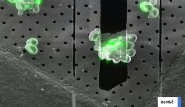
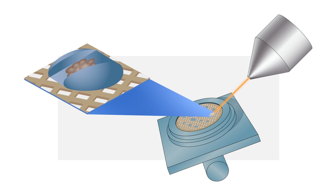
Once the sample is transferred to the cryo-FIB/SEM the first step is to acquire a high-resolution overview image of the grid to determine a milling target. The milling spot should be inside a ~600-μm radius around the grid midpoint to ensure the lamella can be used for cryo-ET. For mammalian cells it is recommended to choose isolated cells to avoid non-vitreous regions. In contrast, small cells like yeast and bacteria should be clustered together to produce a large enough volume to create a lamella. The cells are ideally located within the centre of the grid square mesh covered with intact carbon film to make sure the sample is not lost during sample transfer [1] .
Optionally, cryo fluorescent light microscopy (cryo-FLM) images can be integrated at this point to find a particular region of interest (ROI) and guide the lamella milling [2,3] . Incorporation of cryo-FLM in the workflow can be challenging as it introduces an extra transfer step and thereby increasing the chance of contamination of the sample. Ideally, the sample is also inspected again with a cryo-FLM after milling to ensure the ROI is not milled away [4] . However, this is so risky that this is currently rarely done. To overcome these problems the use of an integrated FLM, such as Delmic’s METEOR system, can be very beneficial.
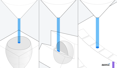
Once the milling target is identified, the milling angle should be determined. The milling angle has a large influence on the length of the resulting lamella: the shallower the milling angle the longer the resulting lamella. Additionally, thin cells, such as a bacterial monolayer, require shallower milling angles than cells larger in height [5] .
Next, the sample needs to be coated with a 1-3 μm thick platinum layer using the gas injection system (GIS) needle. The platinum layer protects the top surface of the sample from being damaged during milling. Moreover, by coating the sample with a platinum layer curtaining artefacts can be avoided and thus higher quality tomograms can be obtained [6] .
Before starting the milling process the milling pattern needs to be defined. It is important to make sure the width of the lamella is smaller than the cell to make sure there is support material for the lamella. The actual milling is done in a stepwise fashion with a decreasing beam current. The steps are often defined as rough milling to ~5 μm thickness, fine milling to ~1 μm and polishing to create a final 100-300 nm thick lamella [7] .
Despite the high vacuum of the cryo-FIB/SEM water molecules from the residual gas inside the chamber can still deposit on the sample and thus on the final lamella. The water deposition results in an ice layer obscuring the final tomogram acquisition. It is therefore recommended to polish the lamellae just before retrieving the samples. This however severely limits the number of lamellae that can be created in a single session. It can therefore be advantageous to install a cold trap inside the FIB/SEM to reduce ice contamination [8] .
Finally, as an optional step, the sample can be sputter coated with a 5-50 nm thick platinum layer. This prevents the build-up of electron or ion-beam charges. The layer can be deposited pre-milling for better FIB/SEM imaging and milling, as well as on the final lamella for better TEM imaging [1] .
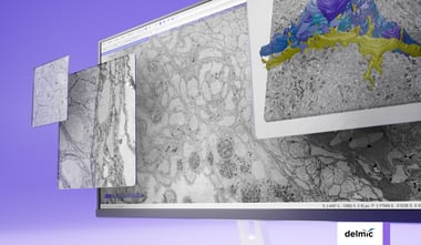
Once all the desired lamellae are created the grid can be transferred to the cryo-TEM and high-resolution data of the cell’s interior can be acquired. Creating lamellae can be a repetitive and time-consuming task, fortunately, there are several methods available to automate this process [9,10]. The process also consists of a lot of transfer steps that pose a chance of contamination. High-vacuum transfer systems are being developed to minimize contamination during transfer [8] . These innovations will make cryo-FIB milling and thus cryo-ET a more accessible and high-throughput technique resulting in more resolved high-resolution structures.
This work is supported by the European SME2 grant № 879673 - Cryo-SECOM Workflow.
References
1 Wagner, F. R. et al. Preparing samples from whole cells using focused-ion-beam milling for cryo-electron tomography. Nature Protocols 15, 2041–2070 (2020).
2 Rigort, A. et al. Micromachining tools and correlative approaches for cellular cryo-electron tomography. Journal of Structural Biology 172, 169–179 (2010).
3 Arnold, J. et al. Site-Specific Cryo-focused Ion Beam Sample Preparation Guided by 3D Correlative Microscopy. Biophysical Journal 110, 860–869 (2016).
4 Klein, S., Wachsmuth-melm, M., Winter, S. L., Kolovou, A. & Chlanda, P. Cryo-correlative light and electron microscopy workflow for cryo-focused ion beam milled adherent cells. Correlative Light and Electron Microscopy IV (Elsevier Inc., 2021). doi:10.1016/bs.mcb.2020.12.009.
5 Villa, E., Schaffer, M., Plitzko, J. M. & Baumeister, W. Opening windows into the cell: Focused-ion-beam milling for cryo-electron tomography. Current Opinion in Structural Biology 23, 771–777 (2013).
6 Hayles, M. F., Stokes, D. J., Phifer, D. & Findlay, K. C. A technique for improved focused ion beam milling of cryo-prepared life science specimens. Journal of Microscopy 226, 263–269 (2007).
7 Schaffer, M. et al. Optimized cryo-focused ion beam sample preparation aimed at in situ structural studies of membrane proteins. Journal of Structural Biology 197, 73–82 (2017).
8 Tacke, S. et al. A streamlined workflow for automated cryo focused ion beam milling. bioRxiv 2020.02.24.963033 (2020) doi:10.1101/2020.02.24.963033.
9 Buckley, G. et al. Automated cryo-lamella preparation for high-throughput in-situ structural biology. Journal of Structural Biology (2020) doi:10.1016/j.jsb.2020.107488.
10 Zachs, T. et al. Fully automated, sequential focused ion beam milling for cryo-electron tomography. eLife 9, 1–14 (2020).