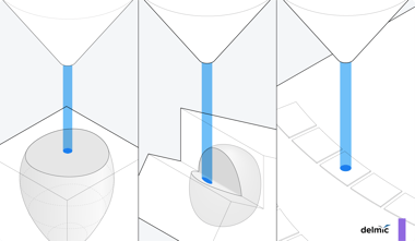
Cryo-electron tomography (cryo-ET) enables researchers to visualize the ultrastructure of biomacromolecules at an atomic resolution. Remarkably, the acquired images represent molecules in their close-to-native state and environment. To preserve the near-native context, cryo-ET users start the workflow by rapidly freezing the intact cells, tissues, or even organisms containing the molecules of interest. The resulting frozen-hydrated samples are however too thick to allow high-resolution cryo tomograms to be acquired. Therefore, one of the important steps in the cryo-ET workflow is to mill the sample to a very thin layer containing the molecules of interest. The ideal lamellae are only 150-300 nm thin, meaning that the milling process has to be extremely precise. Since the focus ion beam (FIB) removes the excessive sample with the required accuracy, this method has been integrated into a scanning electron microscope and the resulting FIB/SEM systems are now more and more commonly used for lamella generation [1]. Using SEM, researchers can visualize the location of the sample on the grid and position the ion beam accordingly. Yet, this information is not enough to guide the milling process so that it would create a thin section of a couple of hundred nanometers containing the biomacromolecules of interest.
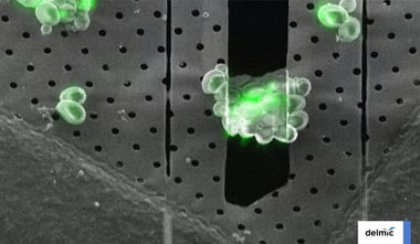
This is where light microscopy, specifically cryogenic fluorescence microscopy (cryo-FLM), comes into play [2]. In this technique, prior to freezing the sample researchers tag the molecules of interest with fluorescent probes. Next, using cryo-FLM they acquire z-stack images of the sample so that they can visualize the 3D distribution of the fluorescent tags and therefore the molecules of interest. Once these images are overlaid with the SEM images of the sample, researchers have sufficient information to accurately define the regions of interest for the subsequent FIB milling. The cryo-FLM images of the resulting lamella can moreover inform if it indeed contains the molecules of interest and is therefore suited ultimately for imaging with the transmission electron microscope.
To assure that cryo-FLM fully benefits cryo-ET users, it is important to minimize the risk of artifacts so as to maximize the targeting efficacy. Artifacts may appear in fluorescence images if the setup is not fully optimized for a specific experiment. Let's explore the two primary sources of artifacts in cryo-FLM and how they can be prevented with an appropriate optics design.
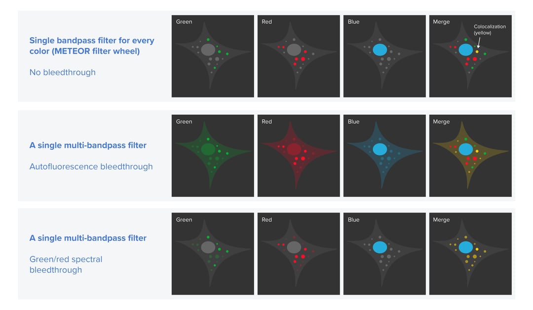
Firstly, we want to prevent excitation crosstalk from occurring in the cryo-FLM images. Excitation crosstalk is an artifact that can appear when two or more fluorescent labels with partially overlapping excitation and emission spectra are used to tag different types of biomacromolecules. In this case, one or more labels may be ‘accidentally’ excited and therefore emit light. If the emission filter in a cryo-FLM system does not allow the applied labels to be clearly distinguished, the resulting images can show false locations of some molecules of interest. This can lead to an erroneous lamella targeting strategy. Excitation crosstalk can happen for example when a multi-bandpass emission filter is used since it is not filtering out the fluorescence that is excited ‘accidentally’. To eliminate this problem, a cryo-FLM system should offer the ability to use and easily switch between different single bandpass filters with spectral properties fitting those of the applied labels. Knowing the excitation and emission spectra of the fluorescent tags as well as the emission spectra of the filters, users can perform multi-channel imaging efficiently and be sure that the cryo-FLM images indicate the true location of their molecules of interest.
The second potential problem in cryo-FLM we want to solve is the overlapping of autofluorescence with the fluorescence of the applied labels. In biological samples, autofluorescence can have various sources, for example, amino acids containing aromatic rings, the reduced forms of pyridine nucleotides, lipid pigments or porphyrins [3]. Typically, at ambient temperatures, autofluorescence is not problematic because it is easily bleached away. In a cryogenic environment, however, it persists. To distinguish the fluorescence of the labels from autofluorescence the samples need to be imaged in two fluorescent channels to allow the autofluorescence to be subtracted [3]. This approach can be therefore only realized in a cryo-FLM system that allows switching between single bandpass filters.
Being aware of these artifacts we designed the emission path in our cryo-FLM system METEOR in a way that makes it easy for the users to prevent the excitation crosstalk and correct the images for autofluorescence. To make sure that researchers can quickly switch between different filters, we implemented a filter wheel that hosts up to four filters. Besides including the most fitting single or multi-bandpass filters, users can also leave one slot free. With such a setup, they can queue up reflected light imaging and multi-channel fluorescence in our ODEMIS software without any physical intervention. Reflected light imaging can give an outline of the cells with low exposure time and allow users to verify the fluorescence coming from within the cells.
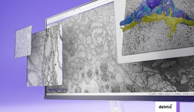
Are you interested to learn more about different correlative cryo-FIB milling strategies using our METEOR system? Check out our white paper below.
References
- Marko et al., Focused-ion-beam thinning of frozen-hydrated biological specimens for cryo-electron microscopy Nature Methods (2007) - link
- Arnold et al., Site-Specific Cryo-focused Ion Beam Sample Preparation Guided by 3D Correlative Microscopy Biophysical Journal (2016) - link
- Carter et al., Distinguishing signal from autofluorescence in cryogenic correlated light and electron microscopy of mammalian cells J Struct Biol (2018) - link