.svg "DELMIC")
.png)


Achieving high-accuracy targeting in cryo-focused ion beam (cryo-FIB) workflows is essential for generating high-quality lamellae for cryo-electron tomography (cryo-ET). But accuracy doesn’t come easy: successful targeting requires more than a high-resolution image.
At every stage in the lamella creation workflow — from identifying the region of interest (ROI) to the final milling step — multiple optical and geometrical challenges affect the accuracy of the targeting. In this blog post, we explore five core challenges to targeting accuracy and how recent advances in integrated fluorescence microscopy are solving them.
1. Fiducials Matter: Why Field of View Influences Correlation Accuracy
Accurate 3D correlation between fluorescence and FIB images depends heavily on the number and spatial distribution of fiducial markers around the ROI. Simply put: the more well-placed fiducials you use, the more precise your targeting will be.
Research supports this:
- Shuoguo Li et al (2023) demonstrated that fiducials should ideally flank the cell containing the ROI — with markers on both sides — to ensure reliable transformation.
- Jan Arnold et al (2016) found that using fewer than six fiducials results in large deviations and inconsistent correlation. However, once six or more are used, the correlation accuracy improves significantly and over 50% of markers fall within a 150 nm error threshold.
- Sven Klumpe et al. (2021) highlighted the importance of an isotropic distribution of fiducials — evenly spaced around the target — to minimize registration error.
This is where field of view (FOV) becomes a critical factor. A larger FOV not only captures more of the sample, but also increases the chance of finding enough well-positioned fiducials around each ROI — ultimately enabling more accurate 3D correlation.
Solution:
Microscopes with a large FOV, such as METEOR 2.0 with a 266 × 266 µm FOV, provide significantly more fiducials per acquisition. This leads to more robust transformation calculations and greater confidence in the 3D correlation process — enabling precise targeting.
 In this example, the smaller FOV only captures 3 fiducials on the right of the cell (not enough for accurate correlation), while the large FOV provides access to > 30 fiducials surrounding the ROI for accurate 3D correlation.
2. Planarity Matters: How Flatness of Focus Affects z-Correlation
Another often-overlooked factor is planarity — how flat the optical focus remains across the entire field of view. Even if resolution is high and fiducials are abundant, uneven focus can introduce axial (z-direction) errors when correlating fluorescence data with FIB images.
Solution:
METEOR 2.0 can achieve a planarity deviation as low as ±50 nm and thus ensures that every pixel in the image lies in the same focal plane. This uniformity is critical for accurate z-correlation and ensures that your FIB targeting is as reliable as your fluorescence imaging.

3. Refraction Matters: Correcting Axial Distortion from Refractive Index Mismatch
Even with perfect imaging and geometry, optical physics can still lead you astray. One major culprit is refractive index mismatch (RIM) between the objective lens (typically in air or vacuum, n = 1.0) and vitrified water (n = 1.28).
This mismatch causes fluorescent emitters to appear shallower than they truly are. In plunge-frozen samples, this distortion can shift the apparent axial position by as much as 2.7 µm — enough to completely miss your ROI when milling a lamella.

Solution:
A two-step strategy, introduced by Daan Boltje and colleagues, addresses this:
- Step 1: Place milling patterns asymmetrically around the estimated position to compensate for depth distortion.
- Step 2: Use an integrated FM to re-correlate after initial milling, once the geometry of the sample has changed and RIM effects are more accurately accounted for.
This approach significantly improves axial targeting.
4. Mechanical Deformation Matters: Why Pre-Milling FM Imaging Can Be Misleading
Even if your targeting is perfect before milling, the physical process of FIB milling can mechanically deform the lamella. These subtle shifts change the geometry of the sample, making pre-milling fluorescence images unreliable for accurate 3D targeting.
As the image below illustrates, the target location may appear at a certain location before milling, but after trenching, mechanical forces can warp the lamella, moving your ROI out of the expected location.
This isn’t just theoretical. A study by Sven Klumpe et al showed that local deformations during milling can shift the region of interest by several hundred nanometers, depending on the grid support type (253–506 nm for titanium SiO2 1/20 and more than 670 nm for gold SiO2 ¼ grids). Displacements were most pronounced in areas of thin ice and along the FIB y-direction.

Solution:
Perform FM imaging after initial FIB milling using an integrated FM system inside the cryo-FIB/SEM. This allows targeting based on the actual post-deformation geometry, not an outdated pre-milling snapshot.
5. Orientation Matters: Imaging from the Milling Angle
In traditional cryo-FM workflows, z-stacks are typically acquired top-down, orthogonal to the grid surface. While effective in some contexts, this approach introduces three key challenges for accurate 3D targeting:
- Limited axial resolution: z-resolution is inherently worse than xy-resolution in fluorescence microscopy, making it difficult to localise features along the depth axis.
- Refractive index mismatch: A recent study from Sergey Loginov et al. shows that the axial scaling factor is depth dependent: it starts to change at approximately 10 µm of imaging depth. This means that compensating for it will be challenging in thicker high-pressure frozen (HPF) samples.
- Orientation mismatch: FIB images are acquired at a shallow angle, not orthogonal to the sample surface. This difference in viewing geometry complicates correlation between FM and FIB images, particularly in featureless HPF samples.
Solution:
A recent study by Matthias Pöge and colleagues demonstrates the advantages of FIB-view fluorescence imaging. By using METEOR’s long-working-distance objective, they acquired FM images in the same orientation as the FIB milling plane. This approach offers several key benefits:
- Reduces RIM-induced axial errors by minimising imaging depth
- Enables direct correlation without reorienting the sample
- Improves targeting accuracy in thick, HPF-prepared specimens
By aligning fluorescence imaging with the actual milling angle, FIB-view imaging offers a more reliable strategy for precise 3D targeting in challenging cryo-FIB workflows.
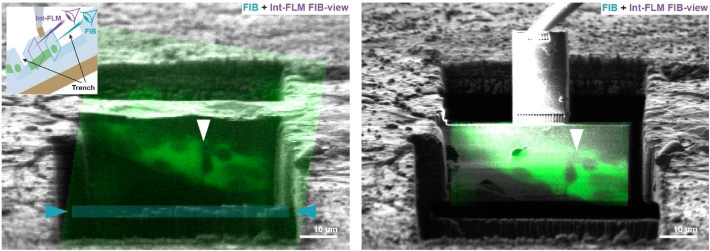
In this example, the authors overlaid FIB images (gray) with METEOR’s FIB-view fluorescence image of cellular autofluorescence (green). Left: before milling the undercut (blue box), right: after milling the undercut.
Conclusion: Toward Truly Accurate Cryo-FIB Targeting
Accuracy in cryo-FIB targeting requires careful attention to both optical and mechanical variables: field of view, focus planarity, refractive mismatch, sample deformation, and imaging orientation all play crucial roles.
By integrating fluorescence microscopy directly into the cryo-FIB/SEM and applying smart imaging strategies before and after milling, researchers can overcome these challenges and unlock more consistent, high-precision cryo-ET workflows.
Ready to improve your targeting accuracy?