In another blog post, we presented all six cathodoluminescence imaging modes that can be used with our SPARC detector to analyze and observe samples. In this blog post, we are going to focus on angle-resolved cathodoluminescence, a technique that allows the creation of angular profiles of the samples.
In cathodoluminescence imaging, the wavelength-dependent intensity (spectrum) is often studied. In addition to the wavelength (color) of the emission, light is also characterized by a wave vector which describes its momentum and propagation direction. The direction in which light is emitted often contains valuable information on how a (nanostructured) object emits and scatters light.
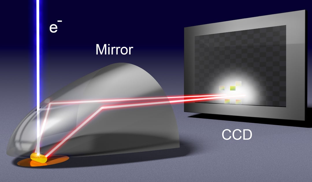
Angle-resolved imaging allows you to acquire this information. In angle-resolved detection, the cathodoluminescence emission is collected from the full beam that comes to the paraboloid mirror. This emission is then redirected out of the SEM chamber toward a 2D CCD or CMOS imaging array. Each point of the acquired image corresponds to a unique emission angle. Emission angles are described by a zenithal angle θ and an azimuthal angle φ and every point in the beam profile corresponds to a combination of these angles.
Therefore, acquired angular profile demonstrates:
- The direction which corresponds to normal emission
- The subsequent rings which correspond to different zenithal and azimuthal angles
When acquiring an angular profile of gold substrate it is possible to see a donut-type pattern (or toroidal emission pattern).
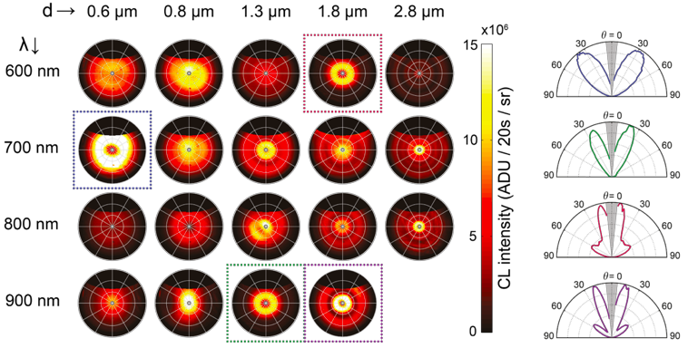
Angular profiles can be effectively used in the field of nanophotonics. One of the materials in can be applied to is plasmonic antennas, which are nano-structures that interact with light and direct it in a particular way. Angular profiles can be measured for different diameters and wavelengths to characterize the performance of the antenna in terms of directivity. Moreover, by moving the electron beam across the structure, from the center to the edge, it is possible to observe how the directivity changes. In this case, an electron beam can be used to simulate the point emitter (such as quantum dots and nano-diamonds) that antennas interact with and probe the performance.
If you would like to know more about angle-resolved CL, make sure to download a dedicated technical note.
Technical note:
Angle-Resolved Cathodoluminescence Imaging
.svg "DELMIC")
.png)